How RTL-SDR dongles work
Pieter-Tjerk de Boer, PA3FWM web@pa3fwm.nl(This is an adapted version of part of an article I wrote for the Dutch amateur radio magazine Electron, November 2019.)
Since 2012, the RTL-SDR is the simple and cheap way to give Software-Defined Radio a try. For about 25 euro you get a receiver covering much of the VHF and UHF range, and by either adding an upconverter, or using the "direct sampling" option, also the HF bands. They are so cheap because they are mass-produced as DVB-T receivers. For use as an SDR, the built-in DVB-T demodulator is switched off, allowing raw data from the A/D converters to go directly to the computer. It turns out that the chip at the heart of these dongles, the RTL2832U, is very flexible, as explained in the sequel.
In essence, an RTL dongle consists of two ICs: the RTL2832U and a tuner chip, for which various types are used. The RTL2832U on has two A/D converters, and a USB interface, and lots of digital logic in between. The tuner chip is an analog downconverter, from VHF/UHF to frequencies of a few MHz, which can be handled by the RTL chip's A/D converters.
Two kinds of tuner chips
Figure (a) shows the blockdiagram of a dongle with the E4000 tuner chip. The frequencies are an example for receving the 2-meter band. The E4000 contains a synthesizer and a mixer. In the example the synthesizer is on 145 MHz, thus converting amateur frequencies between 144 and 146 MHz to between 0 and 1 MHz. In principle this gives us an image problem: for example, both 144.2 and 145.8 MHz are converted to 0.8 MHz. Fortunately, the mixer is a quadrature mixer: that is actually two mixers, getting the same oscillator signal from the synthesizer, but with 90 degrees of phase difference. Both mixer produce the same difference frequency of 0.8 MHz, but the phase difference between them reveals whether the input signal was 144.2 or 145.8 MHz. One could also say that 144...146 MHz is converted to -1...+1 MHz, with the distinction between positive and negative frequencies being made by the phase difference between the quadrature signals. The quadrature signals are called I (for "in phase") and Q ("quadrature").
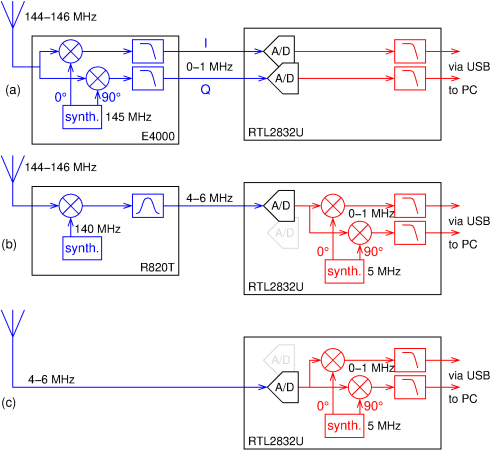 Both the I and Q signals go to A/D converters in the RTL chip.
These A/D converters run at a samplerate of 28.8 MHz.
Because of the Nyquist criterion, they can process input signals up to 14.4 MHz.
This much bandwidth is not needed, so both A/D converters' outputs go to (digital) low-pass filters,
followed by downsamplers (not shown) which lower the samplerate.
The resulting datastream goes to the PC via a USB cable, for further processing in SDR software.
Both the I and Q signals go to A/D converters in the RTL chip.
These A/D converters run at a samplerate of 28.8 MHz.
Because of the Nyquist criterion, they can process input signals up to 14.4 MHz.
This much bandwidth is not needed, so both A/D converters' outputs go to (digital) low-pass filters,
followed by downsamplers (not shown) which lower the samplerate.
The resulting datastream goes to the PC via a USB cable, for further processing in SDR software.
Most tunerchips found in RTL dongles have such a quadrature mixer. But nowadays there are also many dongles with the R820T or R820T2 tuner chip, and those work differently. See figure (b), again using the 2-meter band as an example. We see that in the R820T chip the synthesizer is not on a frequency inside the band of interest, but a few MHz lower: 140 MHz in this example. As a consequence, the amateur band is converted to 4...6 MHz, without image problems, and only one analog signal needs to go the RTL chip. One might expect that signals between 134 and 136 MHz would also be mixed to 4...6 MHz, again giving an image problem. However, it turns out that these signals are suppressed in the tuner: presumably, this implemented by using the quadrature principle again but inside the R820T.
Those 4...6 MHz go to one of the A/D converters in the RTL chip and are sampled there at 28.8 MHz. Next, inside the RTL chip, the signal is digitally mixed with a locally generated 5 MHz signal, with phases of 0 and 90 degrees. Then they are passed through the same low-pass filters and downsamplers as discussed before, and finally via USB to the PC. In the end, we do have a quadrature mixer again, but whereas previously this was analog and inside the E4000 tuner, it is now digital and inside the RTL chip.
Direct sampling
If we take the R820T example, omit the tuner chip, and connect our antenna directly to the A/D converter, then we can receive 4...6 MHz directly, see figure (c). This way of using the RTL dongle is known as the "direct-sampling" mode. We're not limited to the 4...6 MHz frequency range, because although the digital oscillator is on 5 MHz in this example, it is freely programmable: we can receive any desired 2 MHz wide frequency band. We do have to take into account that the A/D converter is running at 28.8 MHz, with which frequencies about 14.4 MHz cannot be distinguished from those below 14.4 MHz. So some analog preselection is needed.
 For direct sampling the antenna must thus be connected directly to the RTL chip.
Luxury dongles are now for sale which, besides other improvements such as more shielding and
a more stable crystal oscillator, bring out this ADC input.
But one can also modify a simpler dongle oneself.
The most logical choice for this is an R820-based dongle: such a dongle only uses one of the two A/D converters for VHF/UHF,
so the other one is still available for the shortwave antenna.
For direct sampling the antenna must thus be connected directly to the RTL chip.
Luxury dongles are now for sale which, besides other improvements such as more shielding and
a more stable crystal oscillator, bring out this ADC input.
But one can also modify a simpler dongle oneself.
The most logical choice for this is an R820-based dongle: such a dongle only uses one of the two A/D converters for VHF/UHF,
so the other one is still available for the shortwave antenna.
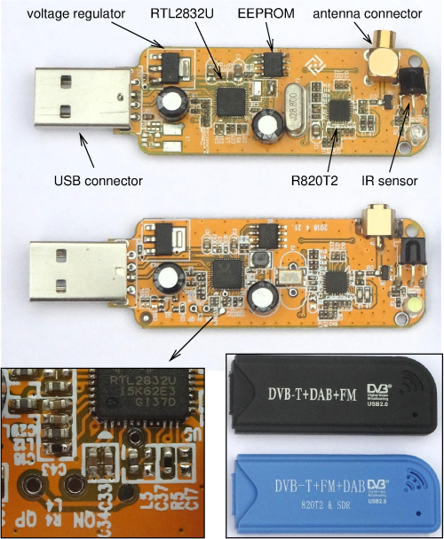
By now, it seems manufacturers are aware of this option. The figure shows the boards from two almost identical RTL dongles, both with the R820 tuner chip. The biggest difference is that in the lower dongle the second A/D input has been connected to solder pads, while with the upper dongle one would have to solder directly to the chip. The solder pads are marked QN and QP, for the Negative and Positive input of the Q channel. These names already indicate that it is a differential input, preferably connected via a transformer. Note also that the cover of the lower dongle features the text "820T2 & SDR". That also indicates that the manufacturer is aware of the use for SDR (besides the "consumer applications" DVB-T/DAB/FM).
Filtering
The low-pass filters, at the right in the block diagrams, have an important task. Up to this point the samplerate is 28.8 MS/s (MegaSamples/second), allowing signals up to 14.4 MHz. But the USB interface is not fast enough for that; more than about 3 MS/s doesn't work. Reducing the samplerate is easy: e.g., discard 9 out of every 10 samples, and you're left with just 2.88 MS/s. But if you do that, you get aliasing. With 2.88 MS/s only frequencies up to 1.44 MHz can be unambiguously represented. Frequencies below and about 1.44 MHz are indistinguishable. So one can only safely reduce the samplerate after a suitable low-pass filter, blocking everything above 1.44 MHz.
 Although I only drew one low-pass filter in each branch, it turns out that in the RTL chip there are two low-pass filters,
one following the other.
The first of them is a 32-tap FIR filter, of which the coefficients can be programmed by the PC.
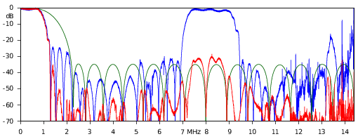
This gives the green curve in the figure: we see it gives about 35 dB of damping in the stopband,
but that stopband doesn't really start until 2.2 MHz.
The second filter is not programmable, but it is steeper: the blue curve (partially coinciding with the red curve).
We see that this passband quickly ends just beyond 1 MHz, which matches well to the samplerate of 2.048 MHz that was used here.
Unfortunately, this filter has a large secondary passband around 8 MHz.
But at 8 MHz the first filter already provides a lot of attenuation.
Taking both filters together gives the red line, providing at least 30 dB of attenuation everywhere above 1.2 MHz.
Although I only drew one low-pass filter in each branch, it turns out that in the RTL chip there are two low-pass filters,
one following the other.
The first of them is a 32-tap FIR filter, of which the coefficients can be programmed by the PC.
This gives the green curve in the figure: we see it gives about 35 dB of damping in the stopband,
but that stopband doesn't really start until 2.2 MHz.
The second filter is not programmable, but it is steeper: the blue curve (partially coinciding with the red curve).
We see that this passband quickly ends just beyond 1 MHz, which matches well to the samplerate of 2.048 MHz that was used here.
Unfortunately, this filter has a large secondary passband around 8 MHz.
But at 8 MHz the first filter already provides a lot of attenuation.
Taking both filters together gives the red line, providing at least 30 dB of attenuation everywhere above 1.2 MHz.
 It turns out that the cut-off frequency of the second filter changes according to the chosen downsampling factor.
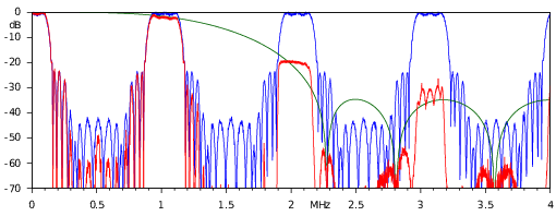
The last figure shows the filter curves when the output samplerate is reduced to just 256 kHz, 8 times lower than in the previous graph.
The green curve (first filter) is the same as previously (but note the different horizontal axis).
The second filter (blue curve) now has a cut-off frequency that is 8 times lower than before,
but the secondary passband that was previously around 8 MHz, also moved down by a factor of 8 to around 1 MHz;
furthermore, it is repeated every MHz.
Because the first filter (green) has not changed, and still doesn't cut off until beyond 2 MHz,
the total filter curve (red) now has a few nasty secondary pasbands.
In practical use this means the dongle does not just receive the desired 256 kHz wide band,
but also 1 MHz above and below.
In principle, this could be remedied by changing the coefficients of the first filter (green) to create a notch
around 1 MHz, but the current driver software does not do this.
It turns out that the cut-off frequency of the second filter changes according to the chosen downsampling factor.
The last figure shows the filter curves when the output samplerate is reduced to just 256 kHz, 8 times lower than in the previous graph.
The green curve (first filter) is the same as previously (but note the different horizontal axis).
The second filter (blue curve) now has a cut-off frequency that is 8 times lower than before,
but the secondary passband that was previously around 8 MHz, also moved down by a factor of 8 to around 1 MHz;
furthermore, it is repeated every MHz.
Because the first filter (green) has not changed, and still doesn't cut off until beyond 2 MHz,
the total filter curve (red) now has a few nasty secondary pasbands.
In practical use this means the dongle does not just receive the desired 256 kHz wide band,
but also 1 MHz above and below.
In principle, this could be remedied by changing the coefficients of the first filter (green) to create a notch
around 1 MHz, but the current driver software does not do this.
A note about where these graphs come from. The green line is the result of a theoretical calculation based on the FIR coefficients that are sent to the dongle by the driver software. The blue and red line were measured on a real dongle. These measurements need to be taken with a suitable grain of salt, firstly because of an AGC that cannot be switched off, and secondly because the data goes to the PC with only 8 bits of resolution. These grains of salt probably explain why adding the green and blue curves does not equal the red curve, as one would expect from two cascaded filters.
Flexibility
It is notable how flexible the RTL chip is. This already starts with the fact that the entire built-in DVB-T demodulator can be switched off, making SDR use possible. The digital quadrature mixer, which originally was intended to support different kinds of tuner chips, can also be used for direct HF reception. Furthermore, the downsampling is configurable: how far the samplerate is lowered after the low-pass filter, which also determines the simultaneously receivable bandwidth. And part of the low-pass filter turns out to be a FIR filter with programmable coefficients, although this flexibility is not exploited by current driver software. Unfortunately, a datasheet of the RTL2832U is not available; most of what is publicly known, has been found out by hobbyists, by studying the manufacturer's drivers and by just trying what happens when writing lots of different values into the chip's configuration registers.With all this knowledge one can also ponder creative alternative ways of using the chip. Configured as in figure (a), the RTL chip in fact works as two synchronous A/D converters, each for signals up to about 1.4 MHz. After removing the tuner one could connect two LF/MF antennas, e.g. loop antennas oriented east/west and north/sound. And with an R820T-based dongle one could simultaneously receive the LF/MF range on one channel and a piece of VHF/UHF via the tuner and the other channel. But such things of course do need modification of the driver software.