Patented RF choke
Pieter-Tjerk de Boer, PA3FWM web@pa3fwm.nl(This is an adapted version of part of an article I wrote for the Dutch amateur radio magazine Electron, January 2018.)
Advance note: the winding shown in the picture is not recommended! I wrote this article to demonstrate that the pictured way of winding is not good, but it seems many viewers of this page think I meant to recommend it...
Many applications need an RF choke which has an impedance of say at least 500 ohm over a large frequency range. An example use of this is supplying power to an active via the coaxial cable which also carries the received signals, for a frequency range of e.g. 100 kHz to 30 MHz. 500 ohms at 100 kHz requires about 800 µH, but an inductor of 800 µH will usually have a self-resonance far below 30 MHz, due to parasitic capacitance.
 Several German radio amateurs (DC5PA, DB0SA, DL4ZAO
see this forum thread)
have found an interesting choke in
US patent 7012485.
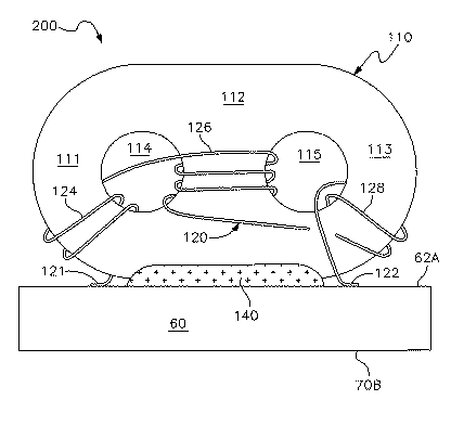
See the figure copied from this patent.
One takes a "pig nose" (binocular ferrite core, i.e. having two holes) and winds a total of 7 turns,
as indicated in the figure: 2 around one edge, 3 around the center, and another 2 around the second edge.
Looking carefully, one sees that the latter 2 turns are opposite to those around the center part;
one can see this by mentally moving them over the core onto the center part.
If the magnetic coupling between the windings around the center and the edge were 100%,
this would make the last 2 turns cancel two of the center turns.
That coupling is less than 100% in reality, so it won't be quite that bad,
but it's still strange.
The idea then is, that although this winding scheme reduces the inductance,
it might result in a much larger bandwidth over which the choke has a sufficiently large impedance.
Several German radio amateurs (DC5PA, DB0SA, DL4ZAO
see this forum thread)
have found an interesting choke in
US patent 7012485.
See the figure copied from this patent.
One takes a "pig nose" (binocular ferrite core, i.e. having two holes) and winds a total of 7 turns,
as indicated in the figure: 2 around one edge, 3 around the center, and another 2 around the second edge.
Looking carefully, one sees that the latter 2 turns are opposite to those around the center part;
one can see this by mentally moving them over the core onto the center part.
If the magnetic coupling between the windings around the center and the edge were 100%,
this would make the last 2 turns cancel two of the center turns.
That coupling is less than 100% in reality, so it won't be quite that bad,
but it's still strange.
The idea then is, that although this winding scheme reduces the inductance,
it might result in a much larger bandwidth over which the choke has a sufficiently large impedance.
However, I have not found any explanation why this would be the case, not even in the patent itself. In fact, the patent's text does not even mention the opposite winding direction. This is only shown in the drawing; the text only mentions the numbers of turns. That is strange, because usually patents tell in sleep-inducing detail everything which is essential and less essential to their claims. The patent's title does call it a "wideband RF choke", but according to the patent's text the wideband nature is due to the fact that in series with this inductor there's a second, differently constructed, miniature inductor, making the combination work up to 10 GHz. So I really wonder whether that opposite winding direction really helps, or is simply a mistake (either by the inventor or by the drawing artist).
To find out, I made coils on two BN73-202 cores (the type recommended by DL4ZAO - the patent does not specify the ferrite), one according to the patent and the other with the "normal" winding direction. The one wound according to the patent has a somewhat lower inductance, 290 µH vs. 390 µH; this was to be expected because the turns partially oppose each other. But apart from that, both coils behave equally well up to 80 MHz (I didn't measure higher). Neither of them has a resonance! And well, the patented winding scheme of course cannot remove a resonance that even the normal winding scheme doesn't have.
These measurements also showed that above a few MHz the coil no longer behaved inductively, but resistively. In other words, current and voltage are in phase, just like at a resistor, instead of having a 90 degrees phase difference as with an inductor. This explains the absence of resonances at higher frequencies. Apparently this ferrite already has such high losses above a few MHz, that the coil no longer behaves inductively. For applications like the phantom power supply that's no problem, quite the contrary. The impedance stays high (a few kilo ohm), without risk of resonance.
 We could also have found the fact that this material has such high losses at higher frequences
in the datasheet.
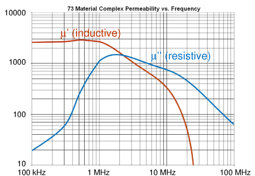
See the figure, based on http://www.fair-rite.com/73-material-data-sheet/.
This graph shows the real (µ') and complex (µ'') part of the permeability
of Fair-Rite's type 73 material.
Practically, µ' is a measure for the amount of inductance per turn,
and µ'' for the amount of resistance due to loss in the material.
Indeed, we see that above a few MHz the loss dominates.
We could also have found the fact that this material has such high losses at higher frequences
in the datasheet.
See the figure, based on http://www.fair-rite.com/73-material-data-sheet/.
This graph shows the real (µ') and complex (µ'') part of the permeability
of Fair-Rite's type 73 material.
Practically, µ' is a measure for the amount of inductance per turn,
and µ'' for the amount of resistance due to loss in the material.
Indeed, we see that above a few MHz the loss dominates.
Conclusion: I haven't found any evidence that this strange winding scheme helps to prevent resonances, at least not in type-73 material. On the other hand, this material, wound either normally or according to the patent, is very suitable for an RF choke for phantom power supply from LF up to HF.
Text on this page is copyright 2017, P.T. de Boer, web@pa3fwm.nl ; the figures are from the sources indicated.
Republication is only allowed with my explicit permission.