The polyphase mixer
Pieter-Tjerk de Boer, PA3FWM web@pa3fwm.nl(This is an adapted version of part of an article I wrote for the Dutch amateur radio magazine Electron, May 2018.)
Mixer with roots in Twente
Two reviews [5,6] of the new Airspy HF+ SDR emphasize that it uses a special mixer, based on a design from the University of Twente (UT) in the Netherlands. This mixer has good large-signal properties and needs less preselection than other mixers because it inherently suppresses harmonics. As my day job happens to be at the UT, though not in the group which designed this mixer, there's ample reason to discuss this mixer here.The mixer is based on work of the IC Design (ICD) group at the UT. Much work of this group is about chips for radio applications, including mixers, and their designs and ideas have ended up in chips used by e.g. many cell phones. And now also in this amateur radio SDR.
(However, sometimes it goes the other way, from amateur radio to science. A couple of years ago I told my ICD colleagues about the "Tayloe mixer", which is popular for homebrew soundcard-based shortwave SDRs like the Softrock designs; it was designed (and patented) by Dan Tayloe N7VE. My discussions with the ICD colleagues led to a joint scientific study of the properties of this circuit [4], and realisation in experimental chips.)
The polyphase mixer
 The mixer in the Airspy HF+ is a so-called polyphase mixer.
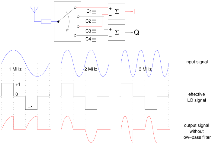
To explain how this circuit works, we first return to the well-known Tayloe-mixer,
see the top-left part of the below figure.
The Tayloe mixer consists of a switch which rotates at a rate given by the oscillator frequency,
and sequentially connects the antenna to the four capacitors.
Each capacitor thus lags its predecessor by 90 degrees.
Differential amplifiers combine the signals that are 180 degrees out of phase;
this leads to two output signals, called I (in phase) and Q (quadrature).
Using those signals, one can distinguish input signals above and below the oscillator frequency (cf. [11]).
The mixer in the Airspy HF+ is a so-called polyphase mixer.
To explain how this circuit works, we first return to the well-known Tayloe-mixer,
see the top-left part of the below figure.
The Tayloe mixer consists of a switch which rotates at a rate given by the oscillator frequency,
and sequentially connects the antenna to the four capacitors.
Each capacitor thus lags its predecessor by 90 degrees.
Differential amplifiers combine the signals that are 180 degrees out of phase;
this leads to two output signals, called I (in phase) and Q (quadrature).
Using those signals, one can distinguish input signals above and below the oscillator frequency (cf. [11]).
A disadvantage of the Tayloe mixer is that it also responds to odd harmonics of the oscillator frequency. This is illustrated in the lower part of the figure. We assume the mixer runs at 1 MHz, so the switch rotates 1 million times per second. We ignore the influence of the resistor and the capacitors and just consider how the signal is "chopped up". We only look at the 0 and 180 degrees outputs (C1 and C3); the other two outputs do exactly the same thing, but 90 degrees later. As the switch rotates, the antenna is first connect to C1 during a quarter of the period, then a quarter period to C2, and so on. The I output signal is the voltage on C1 minus that on C3. Effectively the antenna signal is passed on to the I output during a quarter period, then not during a quarter period, then again during a quarter period but now inverted, and finally again not during a quarter period. In other words, we effectively multiply the input signal by +1, then by 0, then by -1, and finally by 0 again. This is the "effective LO signal" in the figure.
If we take a 1 MHz sine wave as the input signal and multiply this by the effective LO signal, we get the wavevorm at bottom left in the figure: two positive quarter sine waves. After low-pass filtering this (the effect of capacitors C1 and C3), something positive remains. That's good: 1 MHz is mixed to a non-zero DC voltage. If we were to feed 1.001 MHz to the input, its phase would drift w.r.t. that of the 1.000 MHz LO signal; as a consequence, the "DC" output voltage would go up and down with the difference frequency, being 1 kHz, exactly as we expect a mixer to do.
In the center, we see what would happen with an input signal of 2 MHz. We see that multiplying this by the effective LO signal results in a positive and a negative half sine wave. After low-pass filtering, these two halves would cancel, leaving no DC voltage. So this mixer does not respond to the second harmonic.
At the right, we see the same graphs but for an input signal of 3 MHz. Multiplying this by our effective LO signal now results in a somewhat more complicated waveform, which however is more often positive than negative, so also after low-pass filtering something non-zero remains. Thus, our mixer (unfortunately) does respond to signals near the third harmonic of its LO signal.
In practice this means that if one uses the Tayloe mixer to mix e.g. the 7 MHz band to audio frequencies (for further SDR processing via a computer's soundcard), also signals in the 21 MHz band will be received. To get rid of the 21 MHz signals, a low-pass or band-pass filter between antenna and mixer is needed.
This happens because the step-shaped effective LO signal also contains the third (and fifth and higher) harmonics. If we would mix (multiply) by a pure sine wave, without harmonics, this problem would not occur. But technically this is harder to do: it's easier to make a very linear switching mixer than one that multiplies by exactly a sinewave.
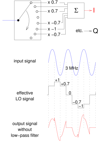 The idea behind the polyphase mixer is to approximate the sinewave by a step-shaped waveform
in which more harmonics are suppressed.
This is sketched in the right-most part of the above figure.
We see that the new step-shaped curve does not have just 4 steps, as in the Tayloe mixer, but 8.
And the levels being used are not just +1, 0 and -1, but also + and - 0.707,
or actually √2/2.
If we do the same calculations as before with a 3 MHz input signal, the resulting output waveform (shown at bottom right)
is even more complicated than before, but this waveform is symmetric:
equally much positive as negative.
After a low-pass filter nothing remains: the mixer no longer responds to the third harmonic!
A different way of understanding this is by observing that the step-shaped effective LO signal now looks
more like a sinewave; so much more that the third harmonic is zero, as in fact are all harmonics
from 2nd up to and including 6th.
The idea behind the polyphase mixer is to approximate the sinewave by a step-shaped waveform
in which more harmonics are suppressed.
This is sketched in the right-most part of the above figure.
We see that the new step-shaped curve does not have just 4 steps, as in the Tayloe mixer, but 8.
And the levels being used are not just +1, 0 and -1, but also + and - 0.707,
or actually √2/2.
If we do the same calculations as before with a 3 MHz input signal, the resulting output waveform (shown at bottom right)
is even more complicated than before, but this waveform is symmetric:
equally much positive as negative.
After a low-pass filter nothing remains: the mixer no longer responds to the third harmonic!
A different way of understanding this is by observing that the step-shaped effective LO signal now looks
more like a sinewave; so much more that the third harmonic is zero, as in fact are all harmonics
from 2nd up to and including 6th.
B.t.w., suppressing harmonics in a mixer by using such a step-shaped waveform seems to have been a hobbyist/amateur invention (in the context of an FM stereo encoder) around 1988, independently re-invented by professionals about 13 years later (see [9]).
One can do even better than with 8 steps. We could use a switch with 16 steps and make an effective LO signal in which even more harmonics are suppressed: with 16 correctly chosen steps all harmonics from the 2nd up to and including the 14th can be suppressed.
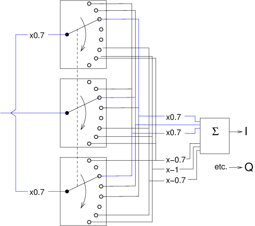 Another option for improvement is sketched in the adjacent figure: we're back to switches with 8 positions,
but we now have three of them.
The coefficients 0.7 and 1 now occur both before and after the switches.
Effectively, we now apply the same step-shaped sequence twice, once before and once after the switches.
Doing it only once, either before or after the switches, already suffices to suppress the harmonics
perfectly; but doing it twice improves the total suppression if the suppression of the separate stages
is not perfect, e.g. due to manufacturing tolerances.
Another option for improvement is sketched in the adjacent figure: we're back to switches with 8 positions,
but we now have three of them.
The coefficients 0.7 and 1 now occur both before and after the switches.
Effectively, we now apply the same step-shaped sequence twice, once before and once after the switches.
Doing it only once, either before or after the switches, already suffices to suppress the harmonics
perfectly; but doing it twice improves the total suppression if the suppression of the separate stages
is not perfect, e.g. due to manufacturing tolerances.
In all these diagrams I purposely didn't specify how to implement those factors 0.7 and the adders in hardware. One could do it with resistors, as in the Tayloe circuit, but in integrated circuits other techniques are preferred, e.g. voltage-to-current converters at the input and current-to-voltage converters at the output as adders. Furthermore, integer coefficients are preferred instead of √2/2 = 0.7071...; e.g. 5/7 = 0.714... or 2/3 = 0.66... . Using these approximations does result in less than perfect harmonic suppression, which again speaks in favor of using two stages as shown above.
The Airspy HF+ features an STA709 made by STMicroelectronics (formerly SGS Thomson). The exact internals of that STA709 are not made public. The small piece of datasheet that is public only shows a very rough block diagram. According to [5] and [6] it contains a polyphase harmonic rejection mixer based on a design of the University of Twente. But this could be realized in different ways; e.g. like Tayloe, directly at the antenna, or with a buffer which can then also give the appropriate multiplication factors (like in the Twente patent [7] or the PhD thesis [8]). According to the Airspy website, "up to" the 21st harmonic is suppressed. But that does not seem to match the statement elsewhere that 16 phases are used, because with 16 phase one fundamentally cannot suppress the 15th and 17th harmonic, because of aliasing. Hopefully someday more information about the innards of this chip will be revealed...
References:
[4] Michiel Soer, Eric Klumperink, Pieter-Tjerk de Boer, Frank van Vliet, Bram Nauta: Unified Frequency Domain Analysis of Switched-Series-RC Passive Mixers and Samplers; IEEE TCAS-I, 2010.
[5] Mike Richards, G4WNC: The Airspy HF+ SDR receiver; RadCom 2/2018.
[6] Nils Schiffhauer, DK8OK: Ein neues SDR-Konzept: Airspy HF+; Funkamateur 2/2018.
[7] Patent US20110298521
[8] Zhiyu Ru: Frequency Translation Techniques for Interference-Robust Software-Defined radio receivers; PhD thesis, University of Twente, 2009.
[9] Pieter-Tjerk de Boer, Mark S. Oude Alink, Eric A.M. Klumperink: Simplified Harmonic Rejection Mixer Analysis and Design Based on a Filtered Periodic Impulse Model; IEEE Transactions on Circuits and Systems II, 2021.