Tubes for phase modulation
Pieter-Tjerk de Boer, PA3FWM web@pa3fwm.nl(This is an adapted version of part of an article I wrote for the Dutch amateur radio magazine Electron, June 2019.)
Nowadays, a small piece of silicon can perform very complicated functions, thanks to thousands or even millions of transistors that can be etched onto it. Those transistors themselves are often boringly identical, but together can do something very complicated. In the tube era, this was different. One can't cram thousands of simple triodes together, but one can do creative things with how electrons move through a vacuum. Thus, special tubes have been made to generate phase modulation.
In the early days of FM broadcast it was difficult to use the "direct" approach to frequency modulation (see previous page), because a free running oscillator, of which the frequency can be modulated, wouldn't be stable enough. In those days, frequency stabilization using a PLL wasn't feasible. That is why the indirect approach was often used, but it turns out that quite a lot of phase shift is needed, many times 360 degrees, to realize enough frequency deviation for FM broadcast. That can't be achieved by just tuning an RC or LC circuit with the modulation: that won't give more than 180 degrees of modulation. Hence the need for special tubes that can produce a much larger phase shift.
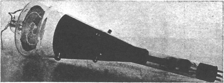 I found a first example of a phase modulation tube in [5] from 1939.
This is a cathode ray tube like those used in oscilloscopes, but instead of a luminous
screen two spiral-shaped metal plates are mounted.
The modulating signal is fed to the deflection plates, with a 90 degree phase shift
between horizontal and vertical.
This will deflect the electron beam such that it paints a circle on the "screen",
i.e., the spiral-shaped plates.
Thus, there is an AC current, alternating between the two plates.
By changing the amplitude of the deflection, the diameter of the circle changes;
due to the spiral shape, this changes the AC current's phase.
I found a first example of a phase modulation tube in [5] from 1939.
This is a cathode ray tube like those used in oscilloscopes, but instead of a luminous
screen two spiral-shaped metal plates are mounted.
The modulating signal is fed to the deflection plates, with a 90 degree phase shift
between horizontal and vertical.
This will deflect the electron beam such that it paints a circle on the "screen",
i.e., the spiral-shaped plates.
Thus, there is an AC current, alternating between the two plates.
By changing the amplitude of the deflection, the diameter of the circle changes;
due to the spiral shape, this changes the AC current's phase.
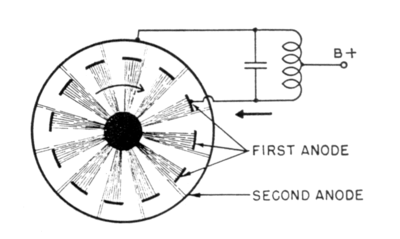
 A totally different phase modulation tube is the "Phasitron", originally
published in 1947 [6].
In the figure we see a number of electron beams going from the
center of the tube to the anodes along the circumference.
Near the center of the tube there are electrodes connected to the transmitter's oscillator,
such that the beams rotate, as indicated by the arrow.
As the beams in the course of the rotation alternately hit one and the other anode,
an AC current is produced whose frequency is the same as that of the oscillator.
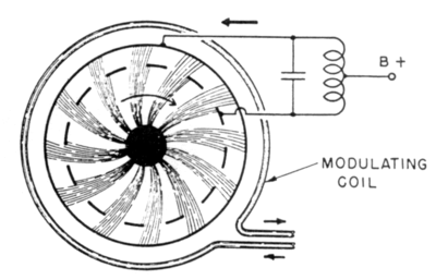
In the bottom figure a coil has been wound around the tube, through which a
current is flowing. This produces a magnetic field, which deflects the electron beams.
Due to this deflection, the beams now reach the anodes at a different location than before,
causing the phase of the anode current to change, proportionally to the applied magnetic field.
Thus, the phase of the anode current can be modulated by varying the current in the modulation coil.
A totally different phase modulation tube is the "Phasitron", originally
published in 1947 [6].
In the figure we see a number of electron beams going from the
center of the tube to the anodes along the circumference.
Near the center of the tube there are electrodes connected to the transmitter's oscillator,
such that the beams rotate, as indicated by the arrow.
As the beams in the course of the rotation alternately hit one and the other anode,
an AC current is produced whose frequency is the same as that of the oscillator.
In the bottom figure a coil has been wound around the tube, through which a
current is flowing. This produces a magnetic field, which deflects the electron beams.
Due to this deflection, the beams now reach the anodes at a different location than before,
causing the phase of the anode current to change, proportionally to the applied magnetic field.
Thus, the phase of the anode current can be modulated by varying the current in the modulation coil.
Whether the tube from [5] (first figure) was ever used in practice, I don't know; this is hard to find out as it was not given a distinct name. However, the Phasitron has really been used, at least one being still in use in 1979 [7].
References:
[5] R.E. Shelby: A Cathode-Ray Frequency Modulator Generator. Radio at ultra-high frequencies, vol. 1, RCA, 1940.
[6] Robert Adler: A New System of Frequency Modulation. Proc. I.R.E. and Waves and Electrons, 1947.
[7] http://www.w9gr.com/phasitron.html